Relay Board Assignments
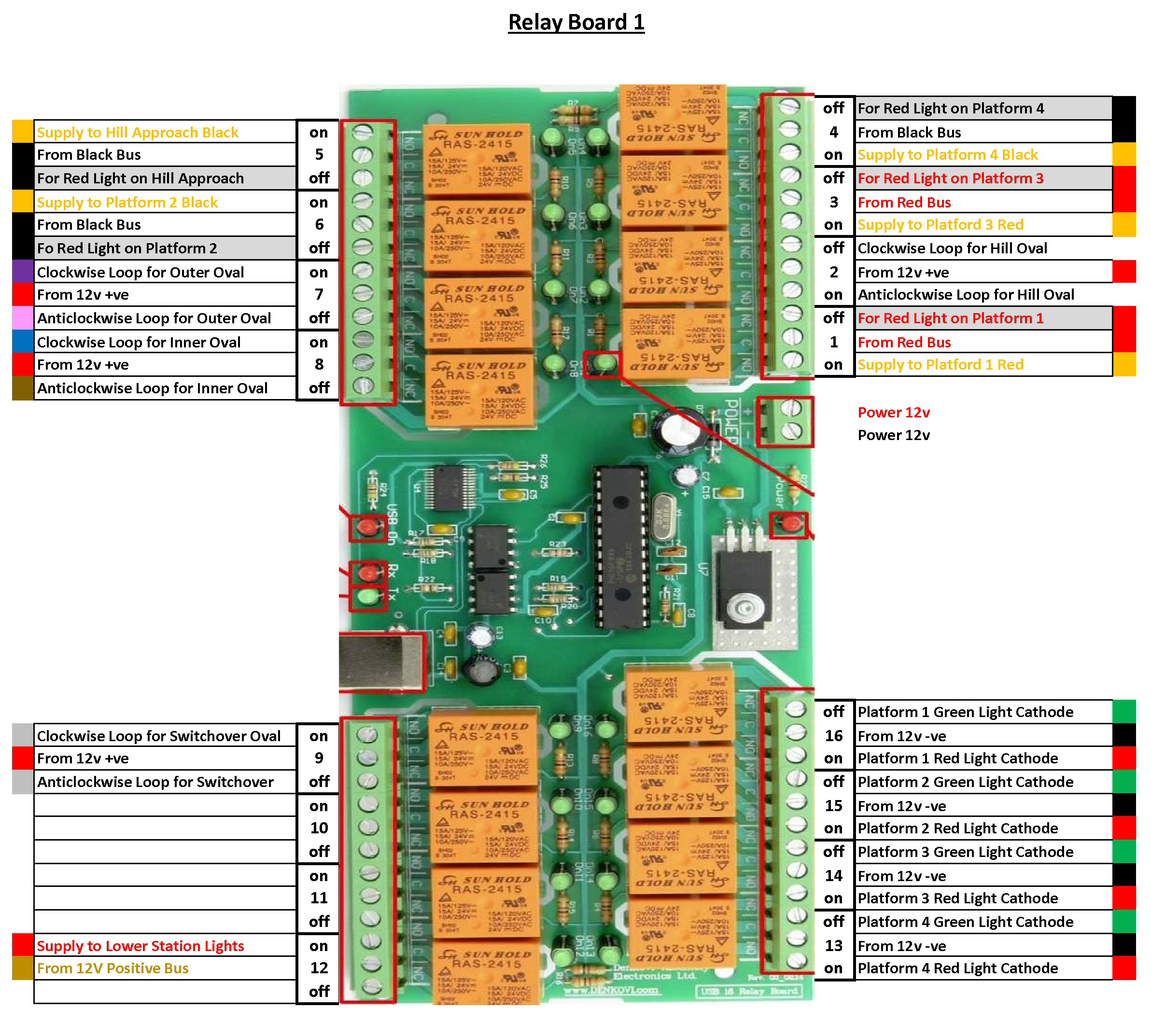
Relay Board 1
Relay board 1 (usually on COM4) provides a mixture of functions
It is used to Power or Isolate track sections at stations, lights, and also the main Clockwise/Anticlockwise power loops for signalling control
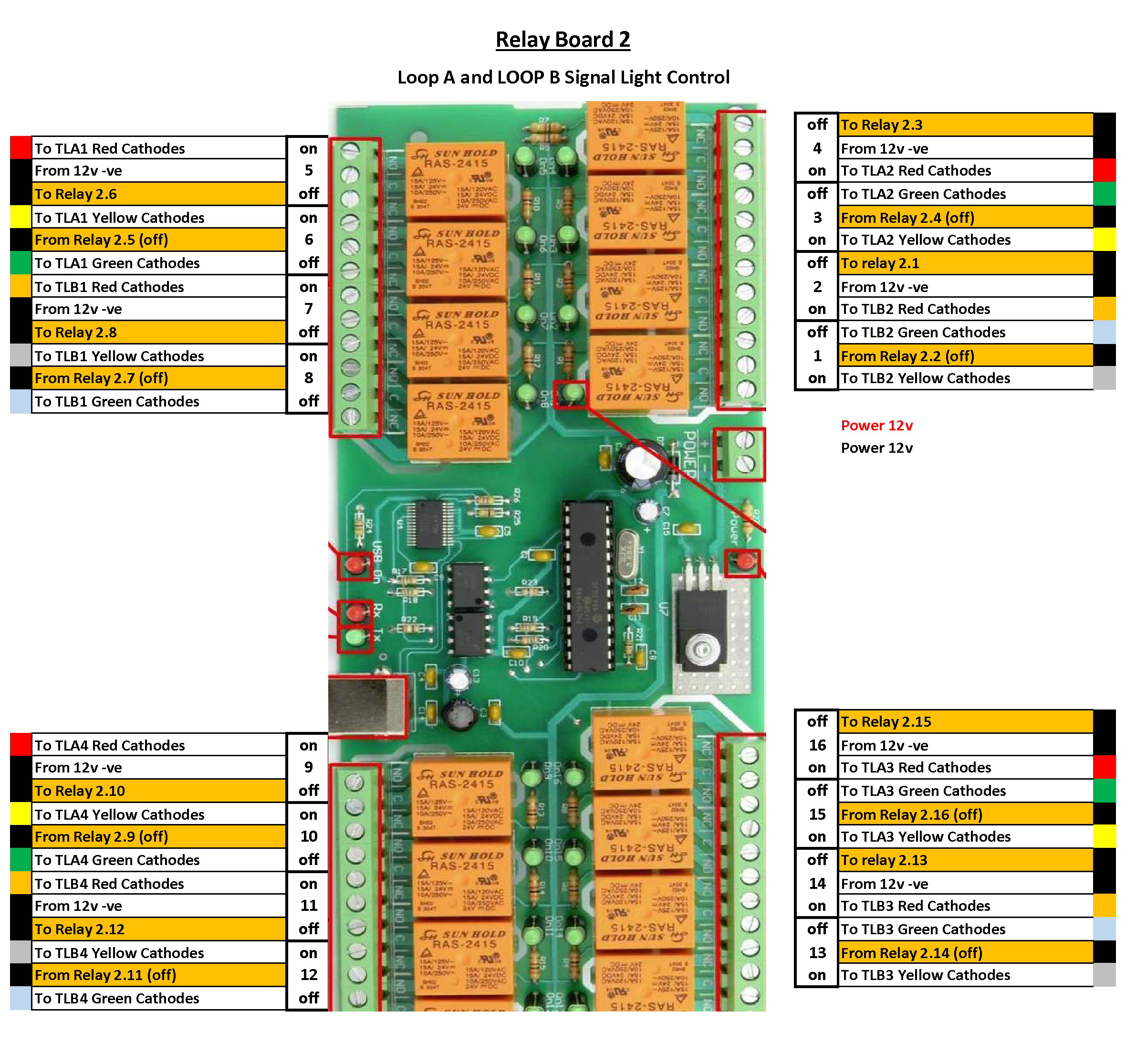
Relay Board 2
Relay board 2 (usually on COM5) provides the signalling control to the Main Outer and Inner Ovals
The 4 sections of the board map physically with the 4 sensor/signalling positions on the 2 ovals using a 12 core shielded cable to link to the 4 signals in each area
Note – Relay boards 2 and 3 only handle the 12v -ve wiring to the led cathodes with the +ve supply to the anodes coming from from relay board 1
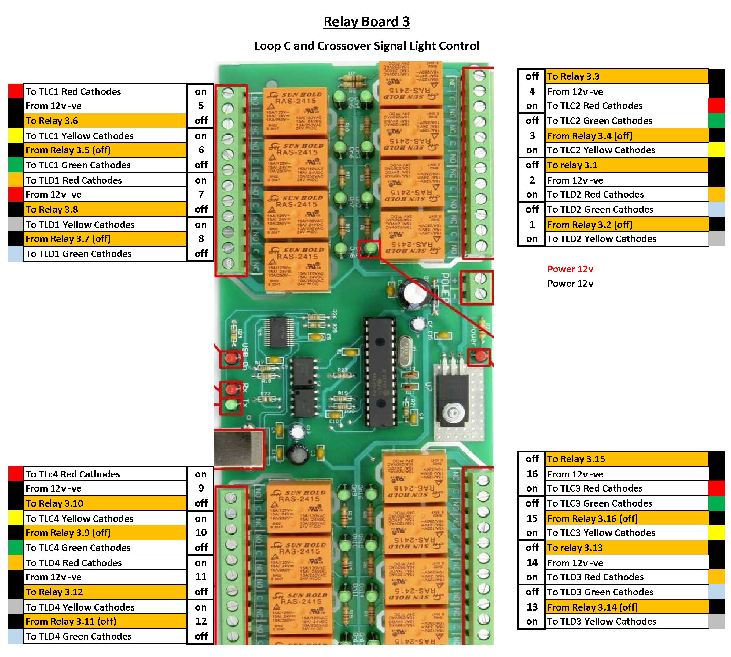
Relay Board 3
Relay board 3 (usually on COM3) provides the signalling control to the Hill Oval and the crossover circuit
The 4 sections of the board attempt to map physically with the 4 sensor/signalling positions as much as possible but these two loops are not a simple rectangular pattern like the two main ovals.
They again use a 12 core shielded cable to link to the signals in each area